Quick Start
The Kerloud VTOL suite is well-tested in factory with real flights, and can provide users a friendly ready-to-fly experience. The quick start procedures include following steps:
Open the box
Sensor calibration (IMU, magnetometer)
Aircraft assembly
Sensor calibration (airspeed)
RC calibration and setup
Battery mounting
Manual flight in position mode (multicopter only)
Autonomous waypoint flight via QGC (Qgroundcontrol station) interface
Open the Box
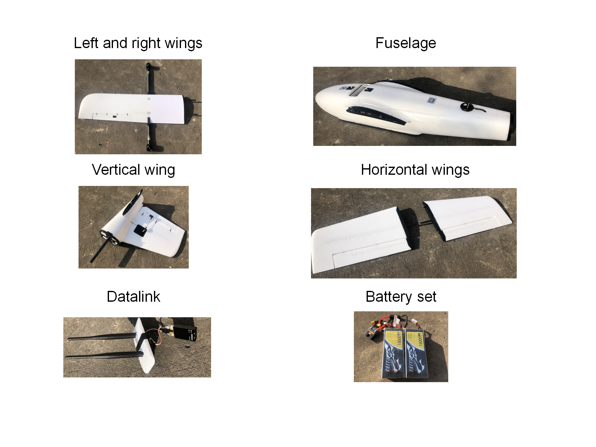
The basic Kerloud VTOL suite consists of following components, and can be assembled in a plug-and-play manner.
Left and right wings
Fuselage
A vertical wing
2 horizontal tail wings
1 datalink set
5 propellers
1 battery set
Sensor Calibration (IMU, Magnetometer)
We first have to conduct sensor calibration for IMU and magnetometer to save some efforts before assembling the whole aircraft. The step is highly recommended due to transport vibrations and district differences. Users can connect the Kerloud autopilot to a laptop running Qgroundcontrol station with a micro usb cable. The official calibration procedure can be referred in the px4 user guide (https://docs.px4.io/).
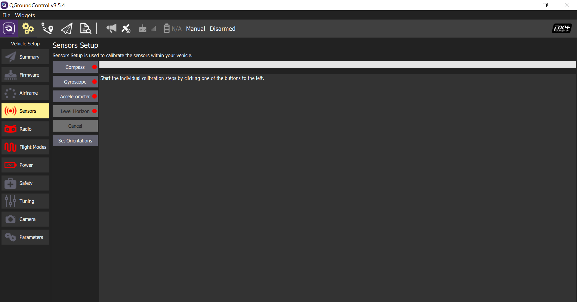
Users should keep the autopilot absolutely static during gyroscope calibration, as even small motion can cause calibration failure or lead to unacceptable gyro bias. The aircraft can be placed on flat table surfaces or vertical walls for accelerometer calibration. Hand-hold calibration is not recommended.
Caution
The airframe setting is configured properly in factory and should not be conducted again. Mandatory setting will cause the loss of onboard parameters, and lead to dangerous flight behaviors.
Hint
A careful sensor calibration will lead to better flight control performance.
Aircraft Assembly
The assembly process is quite straightforward, but the following points are worthy of special attention:
Be certain that all structure parts are mounted rigidly, especially wings.
The datalink cover is advised to be fixed with a paper glue.
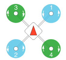
All propellers should be mounted tight to the airframe, and the directions for the multicopter rotors are shown as:
Sensor Calibration (Airspeed)
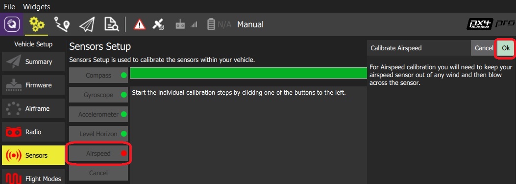
The airspeed sensor is located at the left wing, and users should remove the cover on it.
RC Calibration
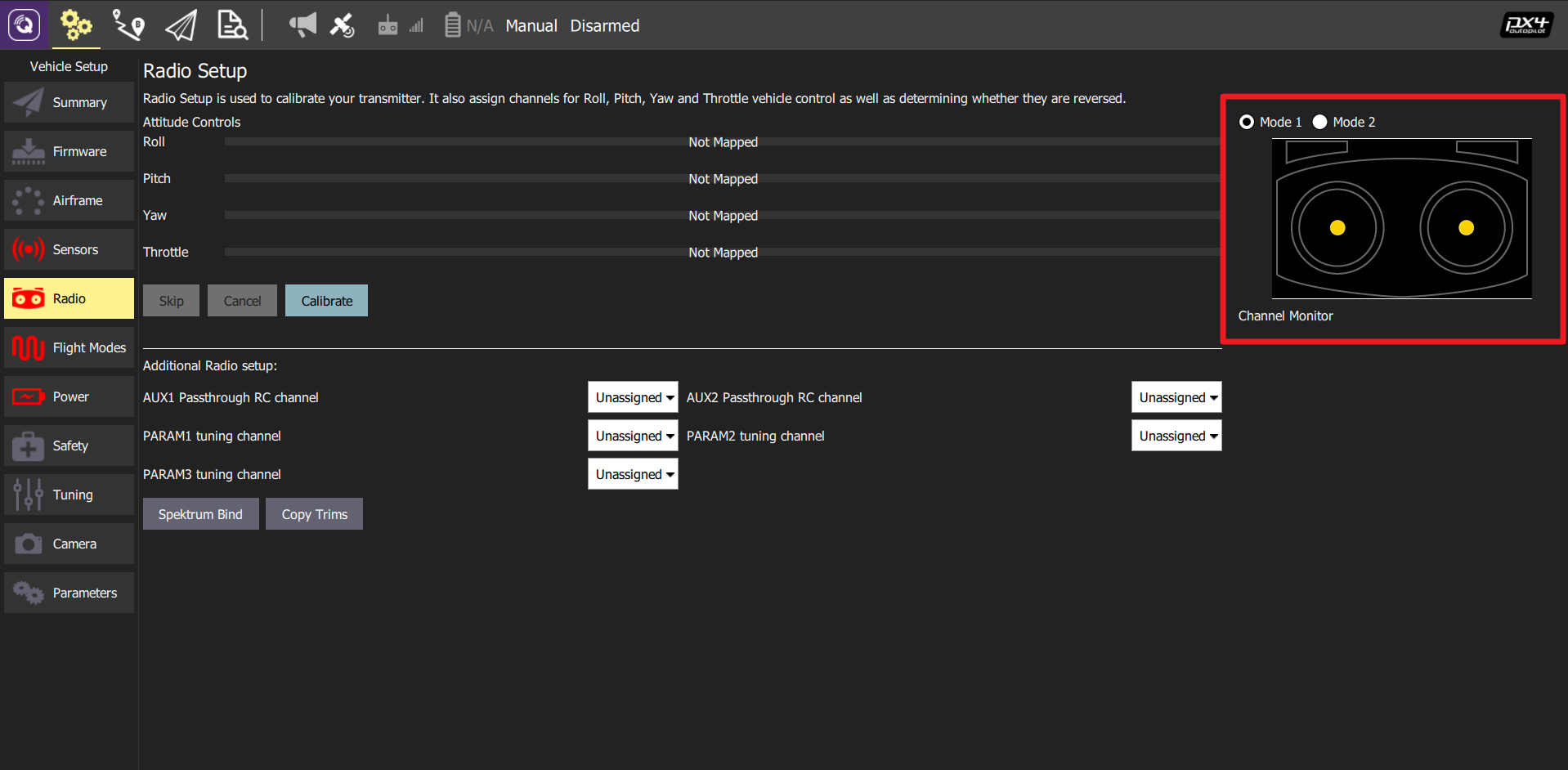
We can select either right hand mode (Mode 1, Japanese Hand) or left hand mode (Mode 2, American Hand) for RC operation. By clicking the Calibrate button, users can complete the procedure easily by following QGC commands.
Flight Mode Setting
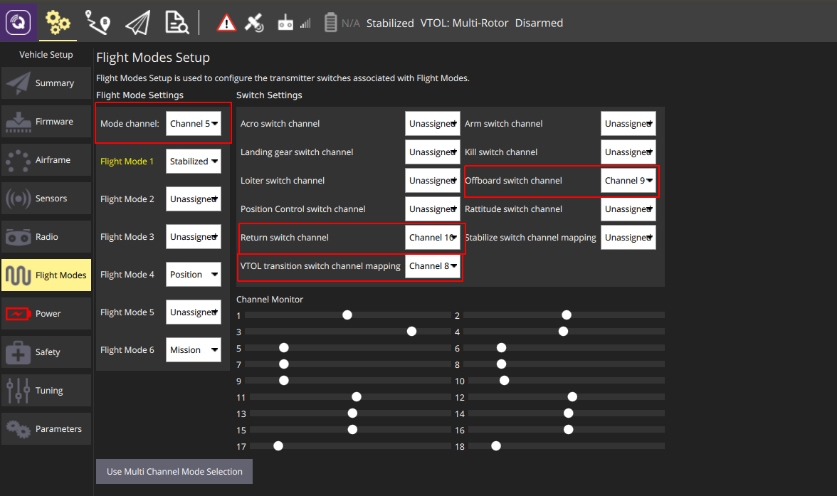
Users should allocate one channel (e.g. channel 5) for flight mode setting, and switch channels for offboard, return home and VTOL transition.
Regarding the flight mode setting, STABILIZED, POSITION and MISSION modes are suggested. The STABILIZED and POSITION modes are used for manual control via the RC transmitter. To highlight here, the STABILIZED mode is for experienced pilots wherein joystick inputs are mapped to the attitude reference, while joystick inputs in POSITION mode are feed into the velocity reference. In the OFFBOARD mode, the UAV is commanded by the onboard computer to achieve autonomous tasks such as waypoint flight, trajectory tracking, and visual tracking, etc. Another mode is called MISSION mode, wherein the UAV will carry out autonomous waypoint flight tasks. Usually the MISSION mode is operated through the ground control station interface.
The return home switch is mainly for safety protection, just in case that the UAV flies out of control.
The transition switch can be used to trigger the mode transition between multicopter and fixed-wing flights, and it is not used in autonomous operations.
Battery Mounting
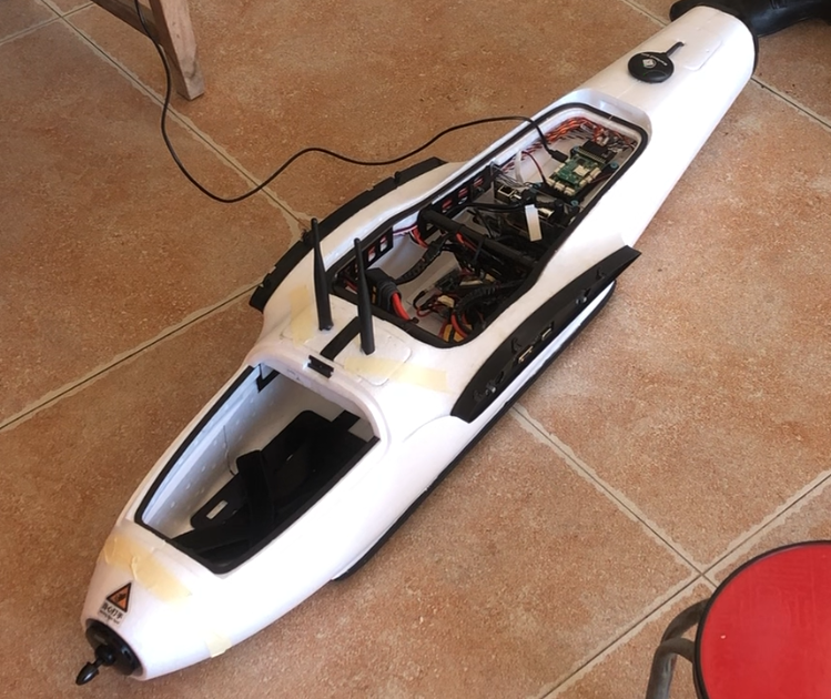
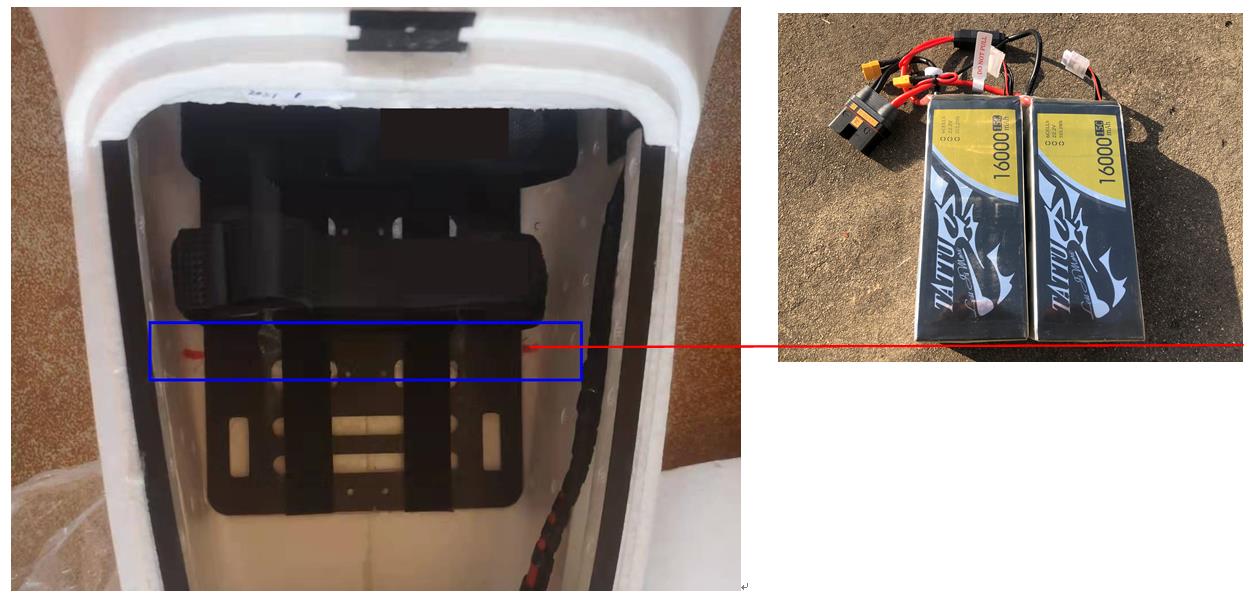
The battery set is a 12S power source, so be cautious during operation. The battery set should be mounted in the airframe with desired CG (center of gravity). For users’ convenience, the head of the battery set should be aligned with marking lines in the fuselage, as shown below:
Manual Flight in Position Mode (Multicopter Only)
The POSITION mode is the easiest way for users to get the machine fly. The basic steps are listed in sequence:
Mount the battery ready, make sure that it will not fall down during flight.
Make sure that all switches are in their initial position and the throttle channel is lowered down.
Power on with the battery.
Wait for the GPS to be fixed: usually we can hear a reminding sound after 2-3 minutes, and the main LED in the GPS module will turn pulsing green.
Make sure that the UAV is in the multicopter mode by viewing the QGC interface.
Arm the UAV by lowering down the throttle and move the yaw stick to the right, then the main LED will be solid green. Pay attention to the channel differences between American and Japanese hands.
Switch to the POSITION mode with the specified stick (e.g. channel 5).
Push the throttle stick slowly above the middle, and the UAV will take off smoothly.
Pull down the throttle stick slowly if we’d like the UAV to land.
Disarm the UAV after it lands successfully by lowering down the throttle and move the yaw stick to the left.
Hint
A minimal distance 3m is recommended for the distance between the ground control station and Kerloud VTOL, and this is to avoid overheat of the telemetry set.
Autonomous Waypoint Flight via QGC Interface
A normal mission for Kerloud VTOL can consist of several waypoints: VTOL takeoff and transition waypoint, waypoint and land, as shown in the figure below. The VTOL takeoff and transition waypoint is advised to be set in front of the home position. The altitude is recommended to be above 30 meters.
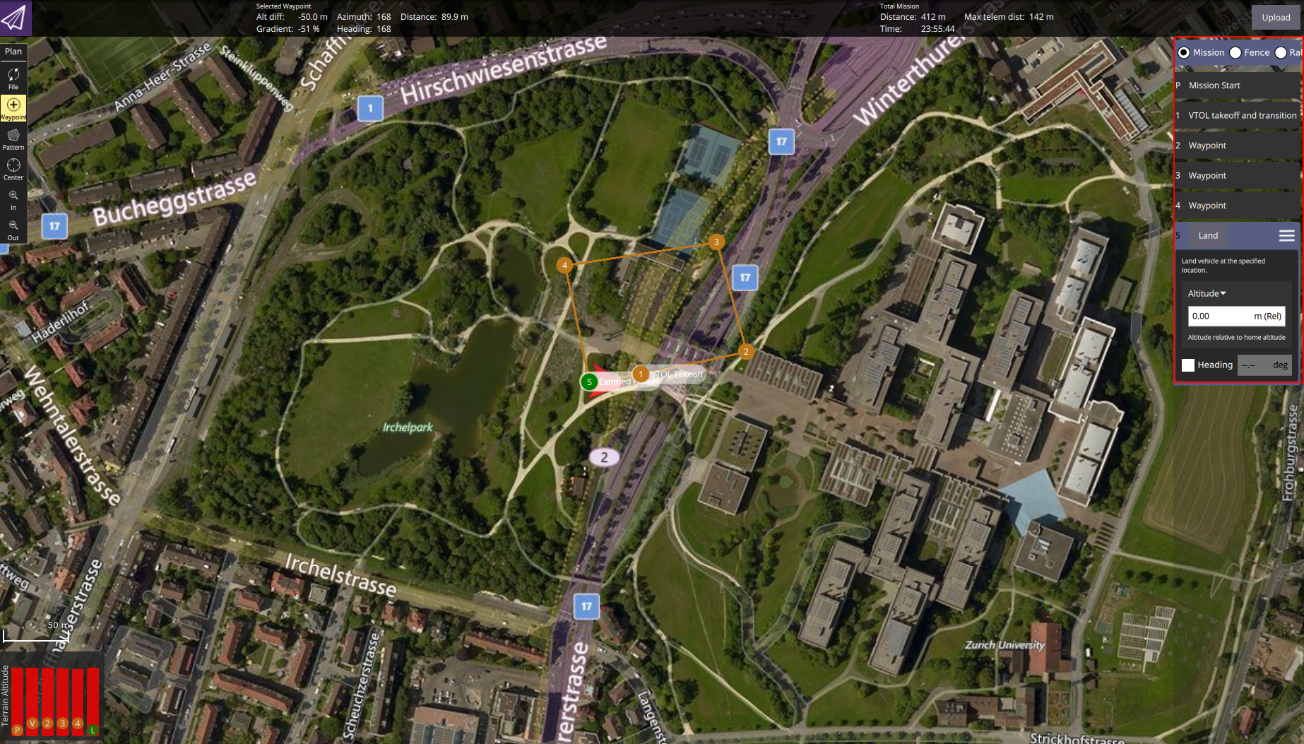
After uploading the mission to the vehicle, users can switch to the mission tab in QGC, and start the mission. The UAV will then carry out the requested mission autonomously.