Realizing Indoor Localization with Onboard Laser SLAM
Note: This tutorial is applicable for Kerloud UAV equipped with a laser scanner.
This tutorial presents how we implement a laser SLAM method for indoor localization.
Caution
The tutorial code is for research project only, and cannot be deployed directly on a product.
1. Hardware Setup and Environment Requirements

The required hardware setup for this tutorial is:
Kerloud UAV with a companion computer such as Nvidia Jetson Nano
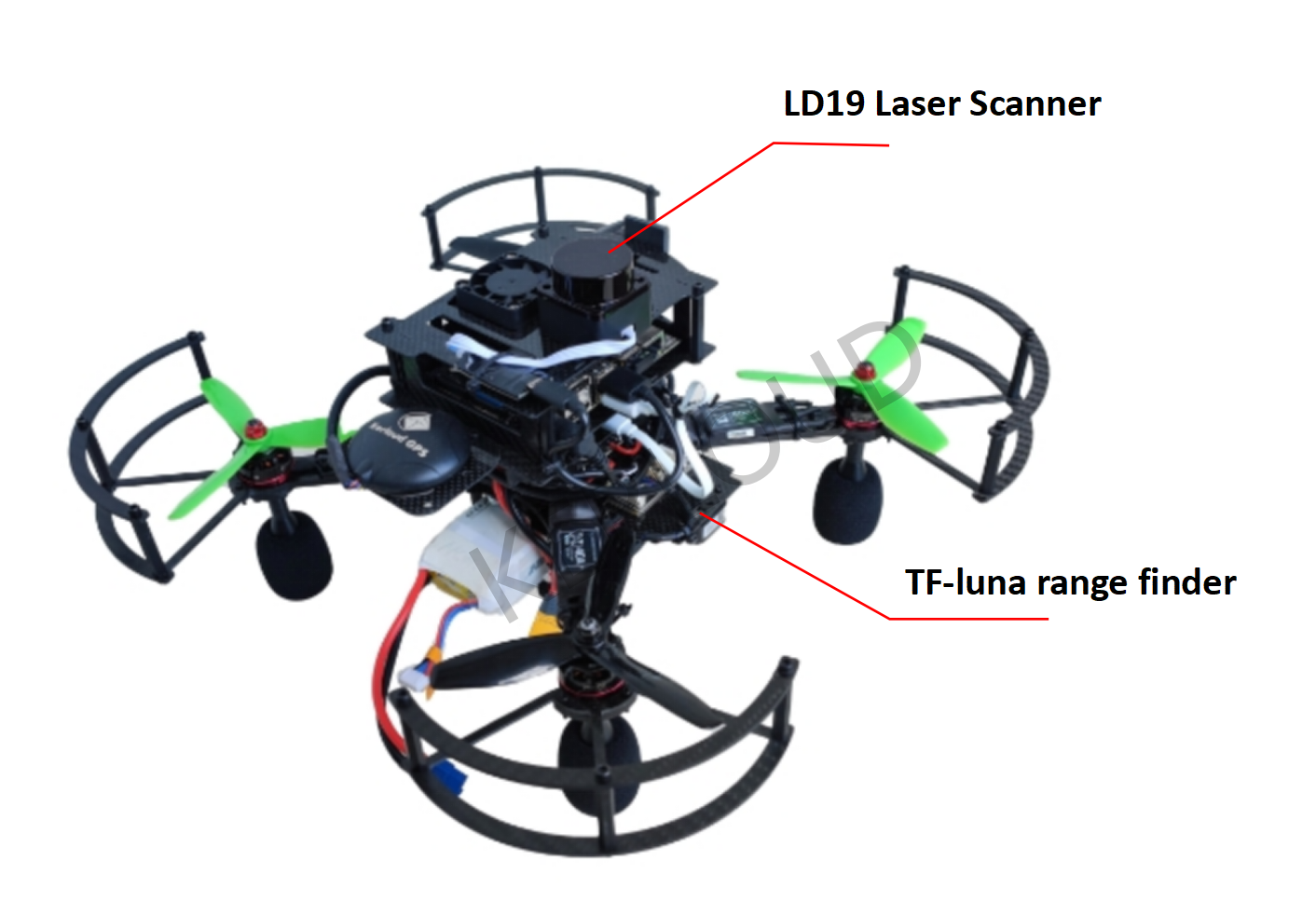
Indoor laser scanner suite including a LD19 laser scanner and Benewake TF-Luna distance sensor
The well-tested environment is ROS Melodic with Ubuntu 18.04, and all necessary components are setup properly in factory.
2. Working Principle
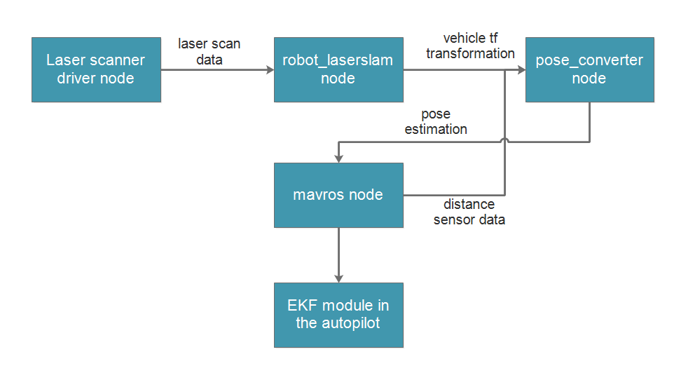
The indoor SLAM process is realized by integrating a 2D laser slam algorithm with an EKF state estimation module in the autopilot. The adopted 2D laser slam algorithm is Google Cartographer, which is a benchmark algorithm in the robotics community. The Cartographer package can output a precise real-time location for the vehicle in the horizontal 2D plane, while the TF-Luna distance sensor provides height measurement. The diagram of the estimation process can be depicted as below:

3. How to Run
3.1 Network Setup for Remote Visualization
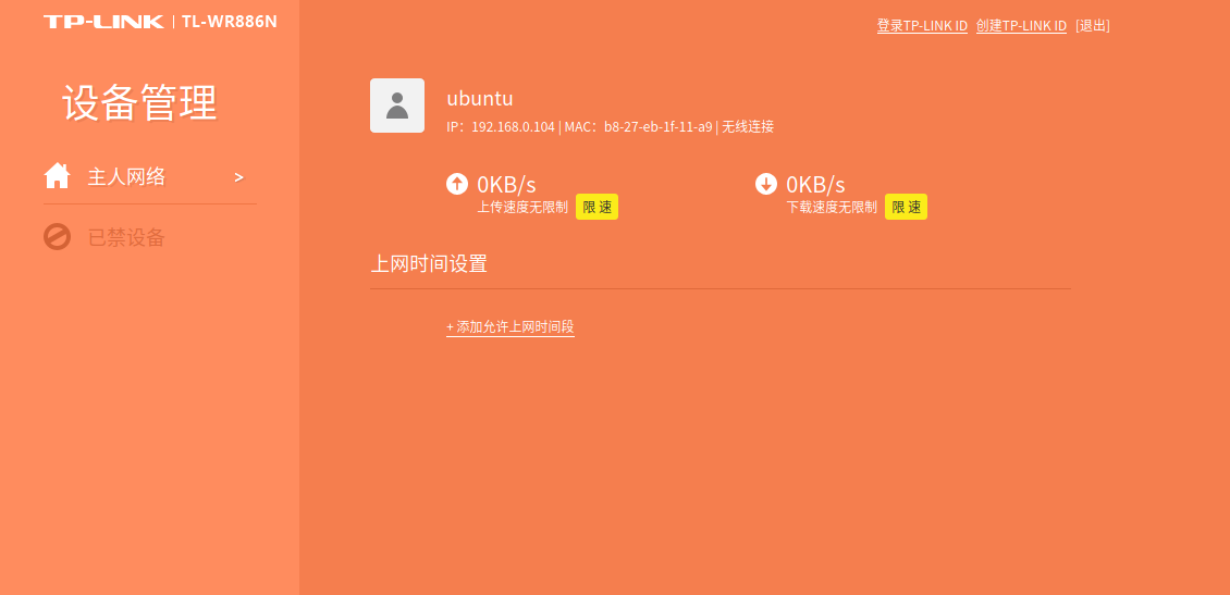
Remote visualization enables a user-friendly experience to access the onboard computer from a remote PC. We first have to connect the onboard computer to a local wifi network once, so that the wifi connection can be automatically setup afterwards. The vehicle IP address can be found by logging into the administration page of the router. Taking the TP-Link router as an example, users can visit 192.168.0.1 or http://tplogin.cn/ to checkout all computers connected in the local network. The computer name and password for the vehicle are both ubuntu by default. The IP address is then displayed as shown below:

After obtaining the IP address, we can set a host IP in both the remote PC and the vehicle with:
sudo vim /etc/hosts

# set a host name for kerloud uav
# e.g. 192.168.0.104 master_ip
<IP address> master_ip
we then set ROS environment variables in the remote PC, while those for the vehicle are set in production:
vim ~/.bashrc

export ROS_IP=`hostname -I | awk '{print $1}'`
export ROS_HOSTNAME=`hostname -I | awk '{print $1}'`
export ROS_MASTER_URI=http://master_ip:11311
Hint
You might also use a mobile phone as a hotspot alternatively to setup the required network;
You have to comment ROS environment settings in ~/.bashrc for the remote PC if you don’t need to connect to the vehicle.
To validate the network connection, we can perform the following commands in the remote PC:
# PC side Terminal 1: setup ssh connection with the onboard computer
ssh ubuntu@master_ip
roscore

# PC side Terminal 2:
rostopic list
If the network is setup correctly, then /rosout and /rosout_agg topics can be viewed in the second terminal above, otherwise an error message will come out as below:
ERROR: Unable to communicate with master!
3.2 Build the Workspace
The ROS workspace for the indoor laser slam is located in ~/src/uav_space/catkinws_laserslam, and it contains several packages:
ldlidar_stl_ros: ros driver for LD19 laser scanner.
robot_laserslam: the laser slam package consisting of configurations, launch files for the Cartographer.
pose_converter: the package to fuse the slam output with the distance sensor measurement, and feed the 3D position to mavros.
To build the workspace, simply run:
cd ~/src/uav_space/catkinws_laserslam
catkin build -j 3
To enable remote visualization, it’s required to copy the workspace to the remote PC as well, and follow the same build process. We assume the workspace is located under the same directory for illustrations later on.
3.3 SLAM Simulation with Datasets
To facilitate the deployment of the indoor slam packages, we provide several laser scan datasets under the directory ~/src/uav_space/catkinws_laserslam/dataset/2D-laser-datasets. Users can launch the laser slam node for these datasets to familiarize those software tools.
The commands to perform the simulation are shown as follows:
# PC side terminal 1: launch roscore after ssh connection
ssh ubuntu@master_ip
roscore

# PC side terminal 2: launch rosbag to play a dataset
ssh ubuntu@master_ip

cd ~/src/uav_space/catkinws_laserslam \
&& cd dataset/2D-laser-datasets \
&& rosbag play floor1.bag --clock

# PC side terminal 3: launch rosbag to play a dataset
ssh ubuntu@master_ip

cd ~/src/uav_space/catkinws_laserslam \
&& source devel/setup.bash \
&& roslaunch robot_laserslam databag_sim.launch

# PC side terminal 4: remote visualization
# users have to copy the workspace from the onboard computer to the PC and build it as well
cd ~/src/uav_space/catkinws_laserslam \
source devel/setup.bash \
&& roslaunch robot_laserslam visualization.launch
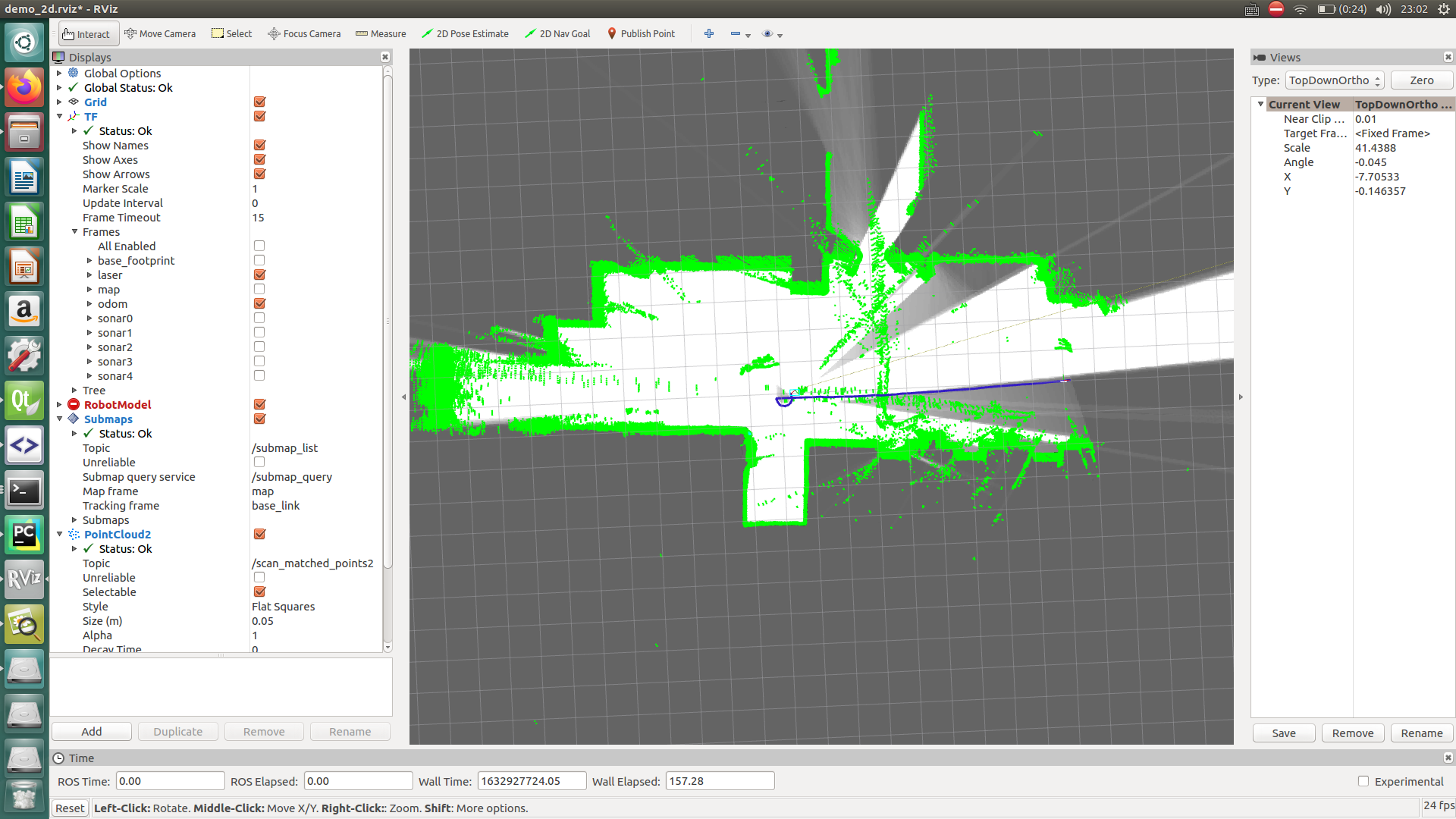
If you follow the above procedures correctly, the rviz window will pop out and show the slam output as below:

To illustrate, the blue line refers to the trajectory of the laser frame, and the relationship between the laser frame and the odom frame reveals the motion of the laser scanner. To view the tf tree of these frames,
rosrun tf view_frames
The tf tree of frames for this simulation is given below for reference (click for a larger view):

3.4 Indoor Experiment
Warning
Please make sure that the Kerloud autopilot is properly configured for SLAM-based localization, and refer to the user manual for details.
To start the laser SLAM process, it’s advised to follow procedures below:
Place the UAV in an indoor environment with surrounding walls and good light condition.
Ensure the battery voltage is at least 16.0V and power up the vehicle.
Set up a local wifi network with a router, and make sure that the onboard computer can connect to it automatically.
Connect the vehicle with QGroundcontrol station, and it’s recommended to calibrate the gyro and magnetometer carefully for the first time.
Start the laser SLAM process remotely with commands below:
ssh ubuntu@master_ip
cd ~/src/uav_space/catkinws_laserslam \
&& bash run_2d.sh
The run_2d.sh script will bring up all nodes in sequence for the indoor laser slam.
It’s optional to start the remote visualization process in the local PC,
cd ~/src/uav_space/catkinws_laserslam \
&& source devel/setup.bash \
&& roslaunch robot_laserslam visualization.launch
Note that the remote visualization can occupy some onboard computation burden, so it’s recommended to turn it off in experiment.
Start a new terminal in the onboard computer, and validate the local position data with:
rostopic echo /mavros/vision_pose/pose
rostopic echo /mavros/local_position/pose
The topic /mavros/vision_pose/pose is the fused position data from the pose_converter package, and /mavros/local_position/pose is the local position from the autopilot. If both topics are correct, the SLAM output can be confirmed.
Then users can operate the UAV in position mode easily, or with their own applications based on our SDK.
References
Map Comparison of Lidar-based 2D SLAM Algorithms Using Precise Ground Truth, https://ieeexplore.ieee.org/document/8581131
Google cartographer documentation, https://google-cartographer-ros.readthedocs.io/en/latest/